AZ480 Steady rest
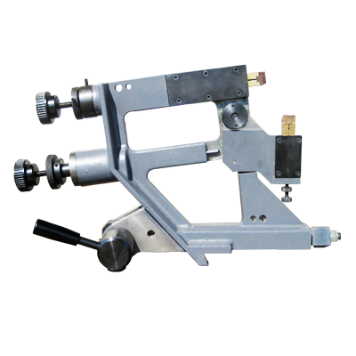
Narrow steady rest (max diameter admitted 100 mm)steady rest contact tips=6x30-steady rest width=12mmStandard steadyrests supplied with AZ crankshaft grinders are of the dial-o-matic type.
This means that the steadyrest may be used for centering adjustments as well as supporting of the work during the grinding process. The picture at the top shows views of a typical design. The parts with numbers designations relate to the support function of the steadyrest and the letters denote those components that comprise the indicator portion.
{tab=Indicator Mechanism}

When the steadyrest is used for centering the dial indicator assembly (A) is moved forward so that the indicator stem (B) is in contact with the back of the upper jaw (8). Any movement of the upper jaw caused by eccentricity in the workpiece will be transmitted to the dial indicator. This will occur as long as the upper jaw is in contact with the workpiece and there is a gap at (F) so that the jaw can move back and forth. Spring (G) will holds the jaw forward so that it will follow the surface being indicated. A locking knob (E) is provided to clamp the indicator in the desired position.Since the indicator is often used on a repetitive basis during the grinding of a crankshaft a small stop rod (D) is provided.This stop can be slid forward and clamped with knob (C).This allows the operator to reposition the indicator in approximately the same relative position for measurements after retracting it. This is invaluable when indexing from one connecting rod journal to the next where it is required that the indicator be brought into position for measurements and then retracted for the grinding operation. For proper function the internal parts of the steadyrest must be flushed out and lubricated daily. WD-40 or similar is recommended. If erratic readings are encountered it is an indication that the internal parts of the steadyrest such as stem (B) may have loosened up during normal use. Access to the indicator mechanism can be obtained by removing the side cover (10).
{tab=Operations}
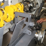
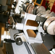
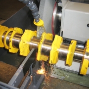
1. In grinding small and short crankshafts, one steadyrest will normally be adequate and should be placed on the main journal closest to the center.
Longer, larger crankshafts may require two or more steadyrests.In any case, before bringing either steadyrest shoe in contact with the journal, be sure that the grinding wheel has removed enough material (using very light pressure)
to create a continuous, concentric surface at least 3/4 of the way around the journal for the shoes to bear against.
First lightly run upper shoe against journal, continue grinding until cleaned up.Then apply lower shoe pressure to control roundness of journal.
2. Proper steadyrest use requires a definite technique which must be acquired through considerable practice.
The function of the steadyrest is to counteract the grinding force and prevent deflection.
Since different grinding conditions will create different deflection forces, the operator must acquire a “feel” for the use of the steadyrest so that the force he uses to oppose the grinding wheel prevents deflection either by the
wheel or the steadyrest.
3. The amount of pressure exerted by the steadyrest shoes should only be enough to hold the journal in its true axis.Excessive pressure will bend the crankshaft causing distortion.
As a general rule the upper shoe maintains very light contact with the journal while the lower shoe must exert a moderate pressure to overcome the weight of the crankshaft.
NOTE: The top shoe is always brought into light contact with the journal first then the lower shoe is brought into contact to support the crank and achieve roundness.
4. The roundness of the surface being ground is primarily controlled by steadyrest technique.Use of a continuous journal sizing gauge (optional) will give the operator a continuous readout of the roundness of the journal as well as its size.
This option will increase operator efficiency and workpiece quality and is highly recommended.
 Italiano


