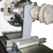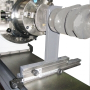
CG2116 Checking square
CRANK POSITION CHECKING SQUARE
{tab=DESCRIPTION}
1. This device is mainly used for setting up of crankshafts during the crankpin or rod journal grinding operation.
This device is constructed so that the “V” position is machined at the same height as the centerline of the crankgrinder
headstock and tailstock.
This allows it to be used for rough setting of journal position at the centerline or grinding use of the appropriate adjustments.
{tab=USE}

The device can also be used for approximate stroke measurement of cranks where the stroke is unknown. a) With the crankshaft to be checked set up for mains grinding, engage the index pins at position “A”. b) Unlock the index lockrings and rotate the crankshaft so that any crankpin is positioned toward the front of machine (1). The stroke axis will be parallel to the table and stroke slide. c) Using the checking square, position the crankpin in the “V” as shown and clamp the index lockrings. d) Loosen the lockscrews on the checking square sliding scale and cursor.
Move the calibrated scale so that the nylon roller at the rear of the scale is touching the front edge of the machine table. Slide the cursor along the scale until it is positioned over the scale “0” and lock the cursor in place. e) Release the index pins, rotate the crank to position “B” (2) and re-engage the pins. f) Slide the checking square forward until it touches the crankpin. As the square is slid forward the nylon roller will pull the scale bacward effectively measuring the stroke of the crankshaft. The reading is taken by noting the dimension indicated on the scale at the cursor.
 Italiano


